
Design and automatic generation of multiline diagrams

CYPELEC Multiline is a program designed to draw, manually or automatically, the multiline diagram of an electrical installation.
CYPELEC Multiline is integrated in the Open BIM workflow via the BIMserver.center platform.
Workspace
CYPELEC Multiline is a program that generates the circuit diagram of an electrical installation. To do so, the program has two complementary work modes:
- Manual layout
Users are responsible for manually introducing the elements and drawing the connection lines that make up the installation. - Automatic import
An IFC filecan be imported into the program via "BIMserver.center". This IFC must contain the BIM model of a single-line diagram and the connection information between phases for each single-phase or three-phase line.
Any program that is capable of exporting an IFC containing information on the single-line diagram and that is included in the Open BIM workflow will be able to benefit from the results output of CYPELEC Multiline. The CYPE programs that generate this information are indicated in the "Advantages of CYPELEC Multiline" section.
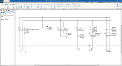
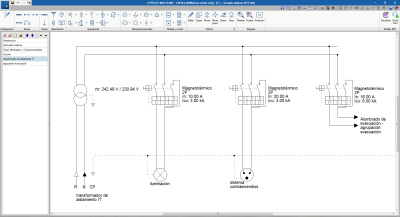
All the protection elements and other equipment linked to each line are reflected in the corresponding span according to their polarity. The symbols used can be chosen from a series of representations drawn from different design codes.
Once the IFC of the BIM model has been imported and the multiline diagram has been generated, users can modify their diagrams using the drawing tools without any restrictions.
Results and generated documents
The results output of the program covers the different drawings that make up the multiline diagram. If an IFC file with the BIM model of an installation has been imported, the program will establish a distribution of drawings, by dividing the diagram based on the subpanels that have been introduced.
Each diagram includes the electrical lines, terminal elements and their corresponding protection switchgear, so this representation is of great interest when it comes to transferring the preliminary design to the execution phase of the connections.
Advantages of CYPELEC Multiline
Other CYPE programs can generate the multiline diagram of the installation, but it cannot be edited by users. As is indicated in the Workspace section, the multiline diagram that is generated in CYPELEC Multiline can be completely edited by users.
The CYPE programs that generate an IFC with the information required for CYPELEC Multiline to generate the editable diagram are:
- CYPELEC REBT (Spain)
- CYPELEC NF (France)
- CYPELEC Core (International)
Users of any of these programs must select the “By phases” configuration option and carry out the design of the installation in this mode before exporting the IFC.
User license
In order to work with the program, the user license must have the “Multi-line diagram” permit.
Tel. USA (+1) 202 569 8902 // UK (+44) 20 3608 1448 // Spain (+34) 965 922 550 - Fax (+34) 965 124 950